Cadillac Lyriq (2022 – 2025) – fuse and relay box diagram
Year of production: 2022, 2023, 2024, 2025
The Cadillac Lyriq, a battery-electric mid-size luxury crossover, has been available from 2022 to the present. In this guide, you will find fuse box diagrams for the 2022, 2023, and 2024 Cadillac Lyriq models, along with information on the locations of the fuse panels inside the vehicle and the assignment of each fuse (fuse layout).
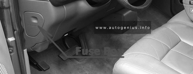
Passenger compartment Fuse Box
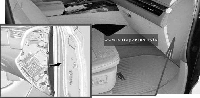
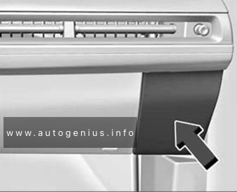
Fuse Box Location
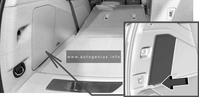
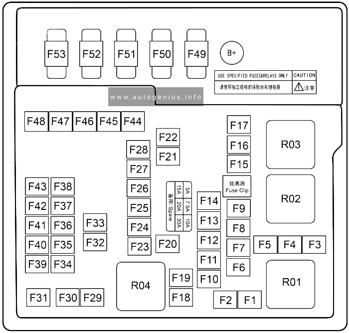
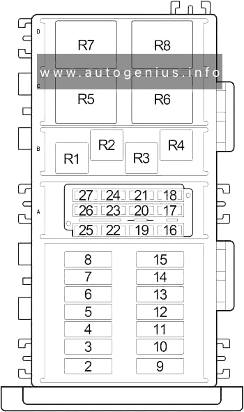
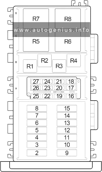
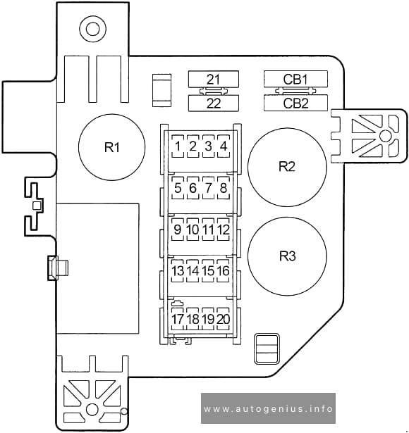
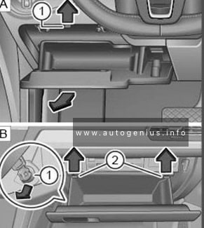
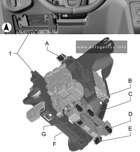
The instrument panel fuse block is to the right of the glove box.
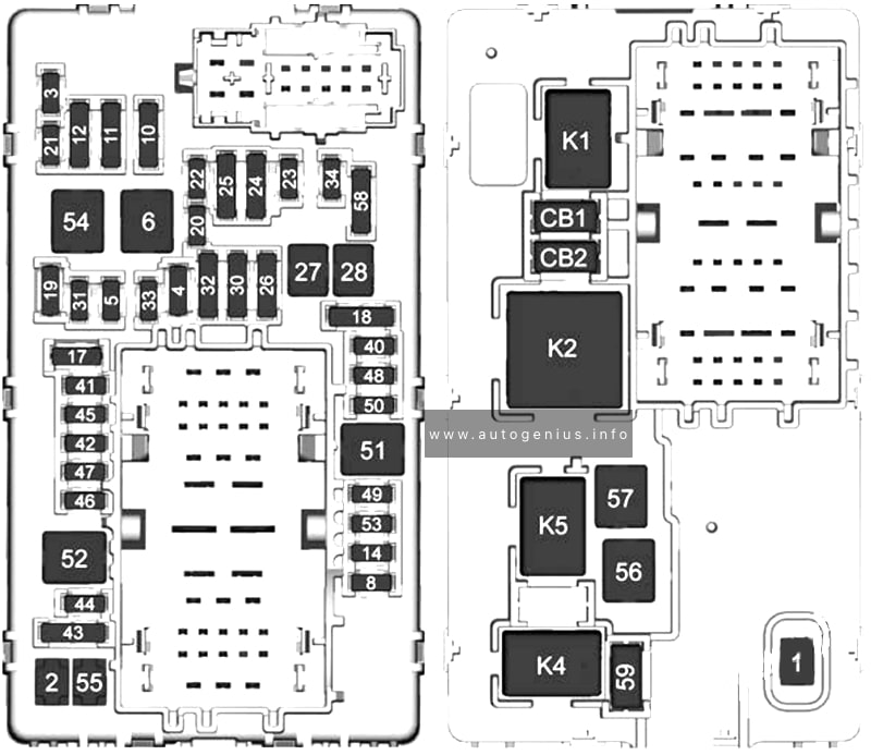
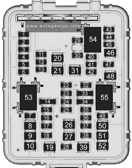
Fuse Box Diagram
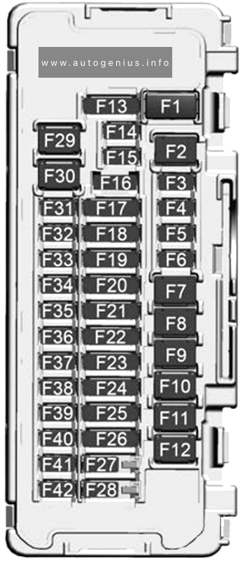
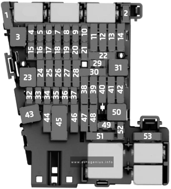
Assignment of the fuses in the instrument panel
| № | Usage |
|---|---|
| F1 | – |
| F2 | Auxiliary Power Outlet Instrument Panel / Cigar Lighter |
| FB | – |
| F4 | Universal Serial Bus Port / Auxiliary Power Outlet Alternating Current 150W |
| F5 | Steering Column Lock |
| F6 | Exterior Lighting Module 1 |
| F7 | Amplifier (Base) |
| F8 | Right Door Latch |
| F9 | Left Door Latch |
| F10 | Steering Column Position Module |
| F11 | Compute Platform 4 |
| F12 | – |
| F13 | Trailer Control and Electrification Control Processor (Traction Power Inverter 1 and 2) / Vehicle Integration Control Module |
| F14 | Headlamps |
| F15 | Headlamp Right |
| F16 | Steering Column Lock / Clock Spring |
| F17 | Seat Fan Passenger and Seat Fan Driver |
| F18 | Virtual Cockpit Display and Short Range Radar |
| F19 | Miscellaneous 2 Switch Bank / Electronic Toll Collection / lnterior Particulate Matter Sensor / Reflective Light Auxiliary Display and Miscellaneous 1 Electronic Brake Control Module / Exterior Lighting Module / Sensing and Diagnostic Module / lnside Rear View Mirror |
| F20 | Body Control Module 1 and Vehicle Integration Control Module |
| F21 | Long Range Radar – Rear and Electric Park Brake Switch / Electronic Transmission Range Select Shifter Module |
| F22 | Virtual Key Module / Virtual Key Backup Module / Auxiliary Jack |
| F23 | Tail Lamp Right and Tail Lamp Left |
| F24 | Universal Park Assist / Automatic Park Assist / Side Blind Zone Alert and Sensing Diagnostic Module / Automatic Occupant Sensing Module |
| F25 | Compute Platform 2 / External Object Calculating Module / Front Camera Module / Multi Function Control and Driver Monitoring System / Central Gateway Module / Diagnostic Link Connector / Vehicle Data Monitor |
| F26 | Electrification Control Processor Battery 2 / Air Condition Electric Compressor and Heads-Up Display / Heating, Ventilation and Air Conditioning Display |
| F27 | Body Control Module 3 |
| F28 | Body Control Module 2 |
| F29 | Amplifier (Uplevel) |
| F30 | Body Control Module 4 |
| F31 | Video Processing Module / SD Card / lndicator Light and Solar Sensor / Over Head Console |
| F32 | Heated Steering Wheel Module |
| F33 | Long Range Radar Front / Light Detection and Ranging |
| F34 | Exterior Lighting Module 2 |
| F35 | Headlamp Left |
| F36 | Virtual Cockpit Unit Battery 1 |
| F37 | Telematics Communication Platform (OnStar) |
| F38 | Wireless Charger Module |
| F39 | High Voltage System Lockout |
| F40 | Virtual Cockpit Unit Battery 2 |
| F41 | Exterior Lighting Module 6 |
| F42 | – |
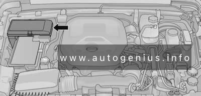
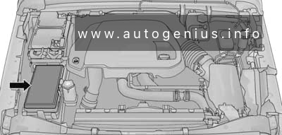
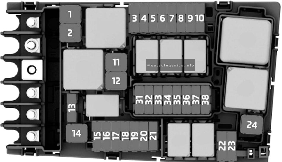
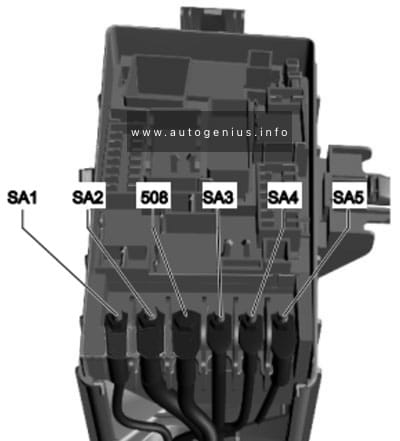
Engine Compartment Fuse Box
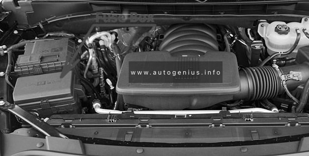
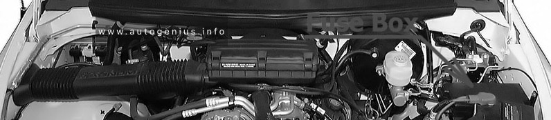
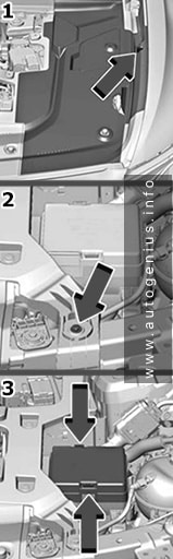
Fuse Box Location
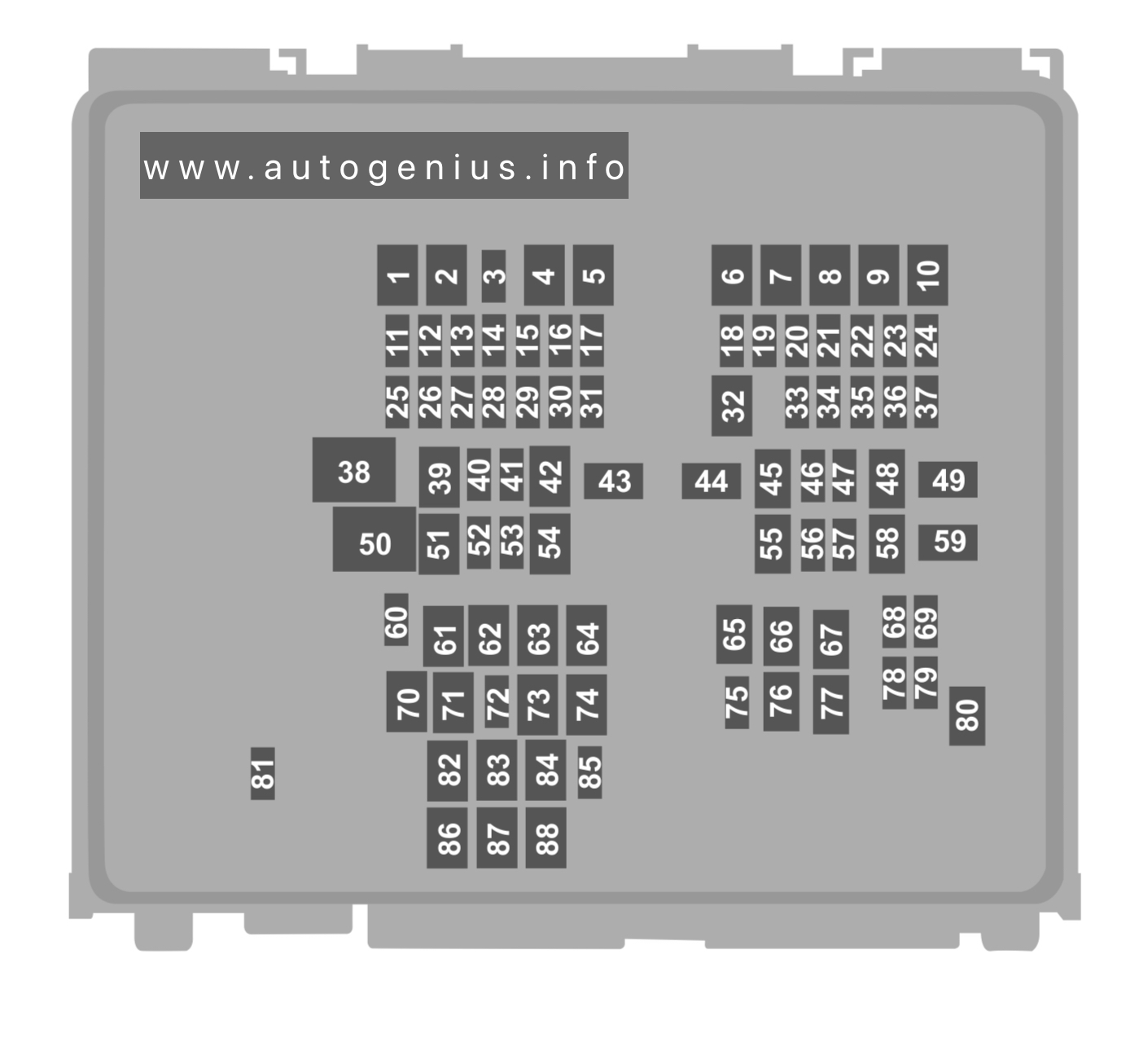
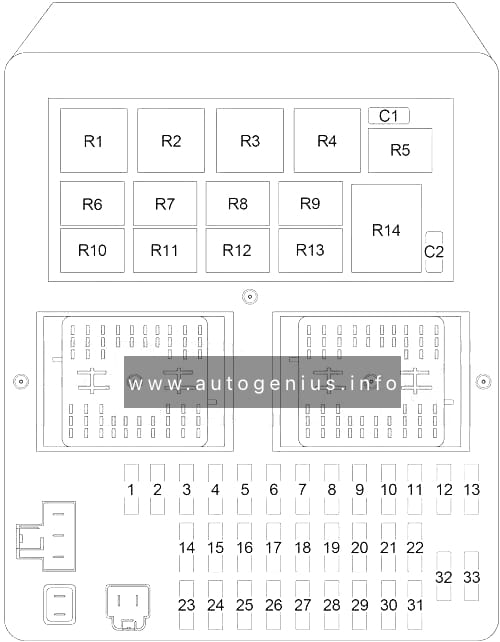
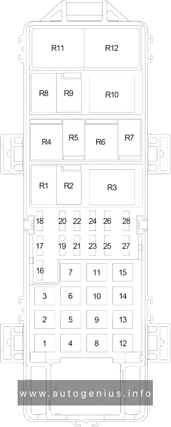
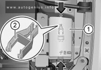
The Underhood Compartment Fuse Block is under a cover and side extension/shield in the underhood compartment.
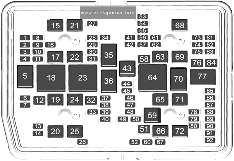
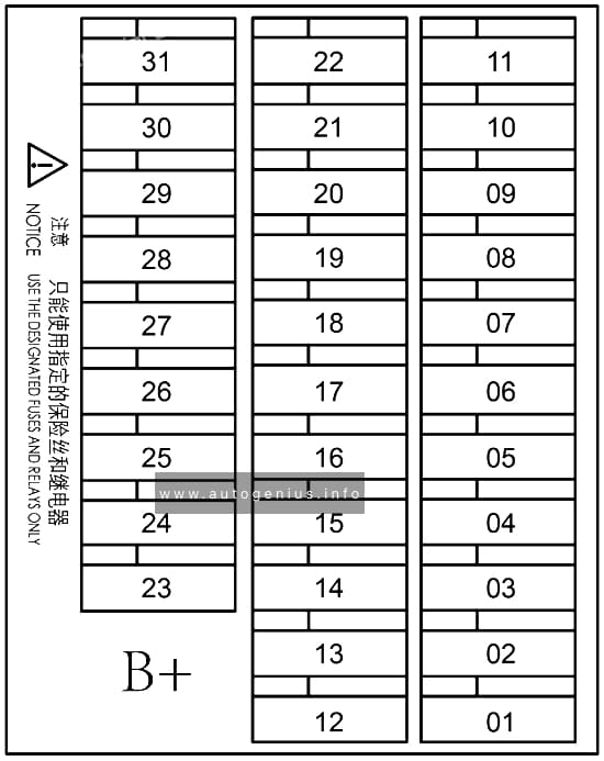
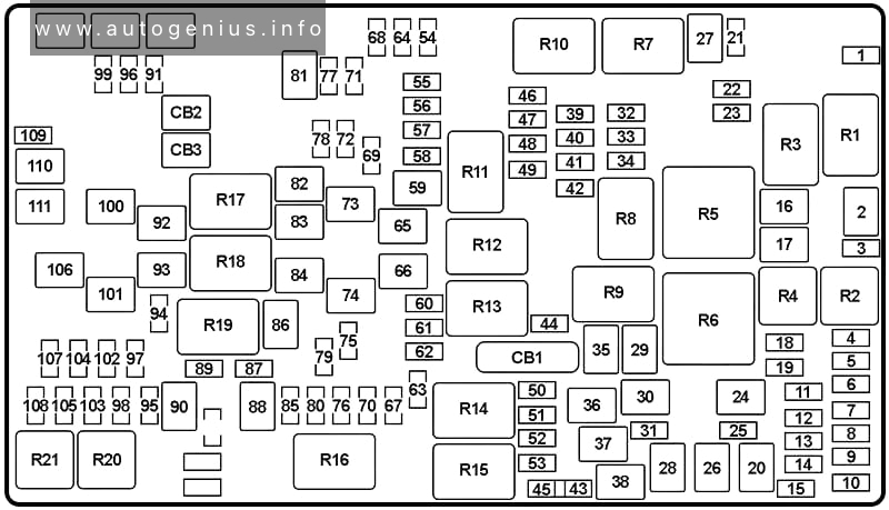
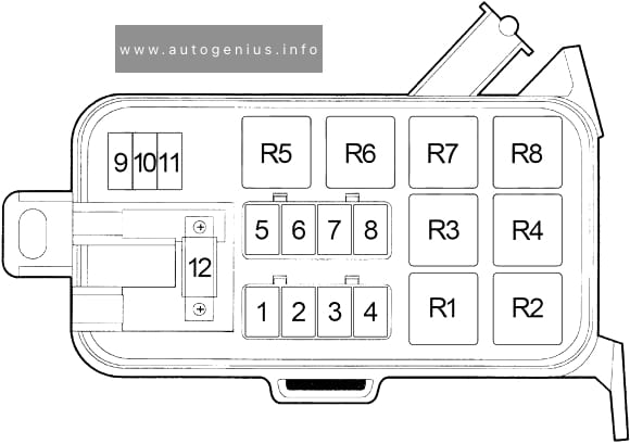
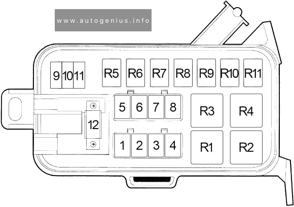
Fuse Box Diagram
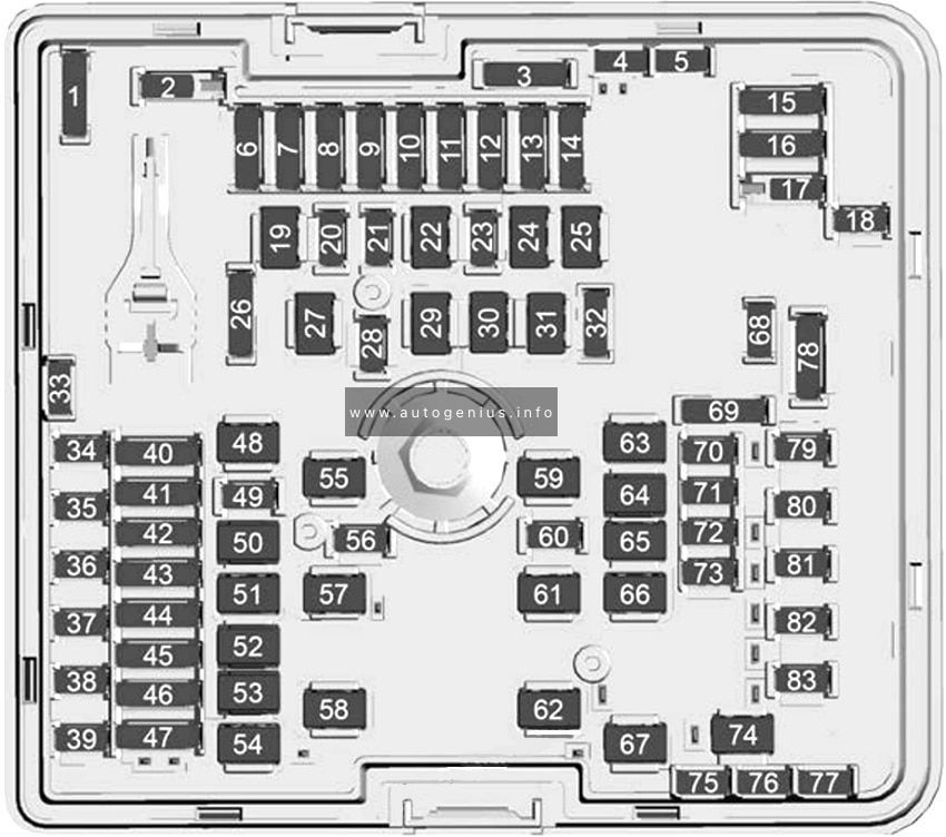
Assignment of the fuses in the engine compartment
| № | Usage |
|---|---|
| 1 | Spare |
| 2 | – |
| 3 | Spare |
| 4 | Spare |
| 5 | Spare |
| 6 | Memory Seat Module / Memory Bolster Module |
| 7 | Primary Evaporator Expansion Valve / Secondary Evaporator Expansion Valve and External Condenser Flow Valve / Condensing Heater Flow Valve |
| 8 | Motor Main Coolant Valve and Air Condition Electric Compressor |
| 9 | Power Electronics Coolant Pump and Energy Storage System Coolant Pump |
| 10 | – |
| 11 | – |
| 12 | Electrification Control Processor (Traction Power Inverter Module 2) & On Board Charging Module 2 |
| 13 | – |
| 14 | – |
| 15 | Trailer Park Lamps |
| 16 | Trailer Reverse Lamp |
| 17 | – |
| 18 | Glove Box Release |
| 19 | – |
| 20 | – |
| 21 | Charqe Port Door Motor |
| 22 | Alternate Current / Direct Current Inverter Module |
| 23 | – |
| 24 | – |
| 25 | – |
| 26 | Spare |
| 27 | – |
| 28 | Electronic Toll Control Module |
| 29 | – |
| 30 | Rear Cargo Auxiliary Power Outlet |
| 31 | Trailer Interface Module Battery Source 1 |
| 32 | Spare |
| 33 | Spare |
| 34 | Exterior Lighting Module 5 |
| 35 | Exterior Lighting Module 4 |
| 36 | – |
| 37 | – |
| 38 | Exterior Lighting Module 7 |
| 39 | Exterior Lighting Module 3 |
| 40 | Electrification Control Processor (Traction Power Inverter Module 1) Source 3 and 1 |
| 41 | Door Switch Panel and Suspension Control Leveling 2 |
| 42 | Seat Position Switch and Virtual Key Module Sensor / Rain Light Humidity Sensor |
| 43 | Steering Column Lock and Charge Interface Module |
| 44 | Power Sounder Module and Aero Shutter |
| 45 | Remote Function Actuator Module and Handsfree Closure Module |
| 46 | Adaptive Forward Lighting / Automatic Headlamp Leveling and Pedestrian Friendly Alert Module |
| 47 | Lit Grille / Front Park Emblem and Semi Active Damping System |
| 48 | Power Tailgate |
| 49 | – |
| 50 | Motor Window Lifter |
| 51 | Suspension Control Leveling 1 |
| 52 | Motor Window Lifter Riqht |
| 53 | Front Wiper |
| 54 | Trailer Battery |
| 55 | – |
| 56 | Fold Seat Riqht Motor |
| 57 | Electronic Brake Control Module |
| 58 | Front Blower Motor |
| 59 | – |
| 60 | Horn |
| 61 | Rear Defog |
| 62 | Rear Blower Motor |
| 63 | Motor Sunroof and Motor Sunshade |
| 64 | Power Seat Driver |
| 65 | Power Seat Passenger Driver |
| 66 | Condenser Radiator Fan Module |
| 67 | Heated Wiper |
| 68 | Spare |
| 69 | Spare |
| 70 | RELAY’S COIL |
| 71 | Rear Heated Seat 2 |
| 72 | Front Heated Seat 1 |
| 73 | Fold Seat Left Motor |
| 74 | Trailer Interface Module Battery Source 2 |
| 75 | Spare |
| 76 | Spare |
| 77 | Spare |
| 78 | Trailer Stop Turn Left and Trailer Stop Turn Right |
| 79 | Rear Heated Seat 1 |
| 80 | Front Heated Seat 2 |
| 81 | Out of Park Disable |
| 82 | Wash Pump (Front) |
| 83 | Camera Wash |
| 5 | — |
| 18 | DC/AC Inverter |
| 23 | 2022: Fuel Heater |
| 35 | Trailer Park Lamp |
| 36 | Run/Crank |
| 43 | Secondary Axle Motor |
| 59 | A/C Clutch |
| 64 | Starter Motor |
| 70 | Starter Pinion |
| 77 | Powertrain |
WARNING: Terminal and harness assignments for individual connectors will vary depending on vehicle equipment level, model, and market.