Volkswagen LT (2D; 1996 – 2006) – fuse and relay box diagram
Year of production: 1996, 1997, 1998, 1999, 2000, 2001, 2002, 2003, 2004, 2005, 2006
This article focuses on the second-generation Volkswagen Transporter LT (Typ 2D), which was produced between 1996 and 2006. It includes fuse box diagrams for Volkswagen LT models from 1996 through 2006, along with information on the location of the vehicle’s fuse panels. You will also find details on the fuse and relay assignments (fuse layout) for each model year.
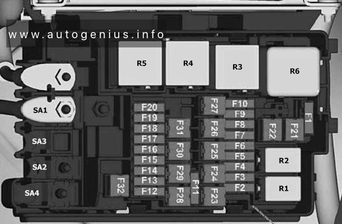
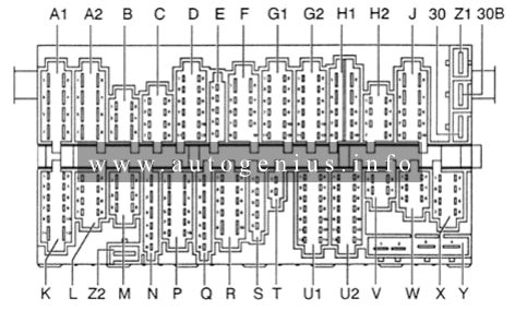
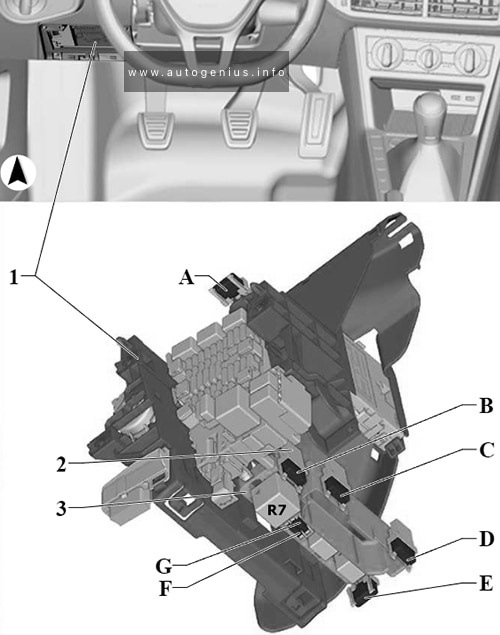
Passenger Compartment Fuse Box
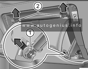
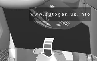
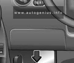
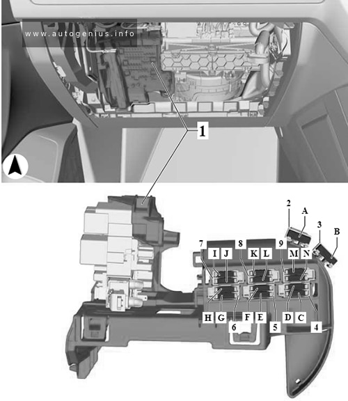
Fuse Box Location
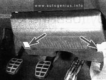
The fuse box is located behind an access panel in the steering column.
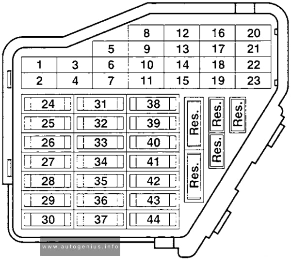
Fuse Box Diagram
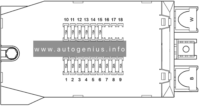
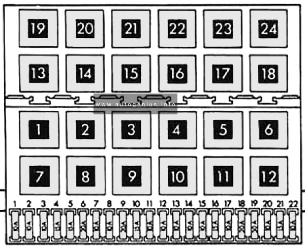
Assignment of the fuses in the instrument panel
| № | Amps | Description |
|---|---|---|
| 1 | 15A | Right side and tail lights |
| 2 | 15A | Right main beam (56a) |
| 3 | 15A | Left main beam (56a), warning light |
| 4 | 15A | Reversing lights |
| 5 | 15A | Brake light |
| 6 | 20A | Window wash/wipe system |
| 7 | 15A | Horn (15), self-diagnosis (15), terminal 15 relief relay, fresh air and recirculating air flap two-way valve, dash panel insert, heated rear window |
| 8 | 20A | Interior lights, cigarette lighter, radio system (30), self-diagnosis (30) |
| 9 | 15A | Analogue clock, hazard warning system, parking light |
| 10 | 15A | Instrument lighting, number plate lighting (58) |
| 11 | 15A | Left side and tail lights (58L) |
| 12 | 15A | Right dipped beam (56b) |
| 13 | 15A | Left dipped beam (56b) |
| 14 | 15A | Fog light, rear fog light |
| 15 | 15A | Radio system (15) |
| 16 | – | Free for optional equipment |
| 17 | – | Free for optional equipment |
| 18 | – | Free for optional equipment |
| B | Hazard warning light relay | |
| W | Wiper motor relay |
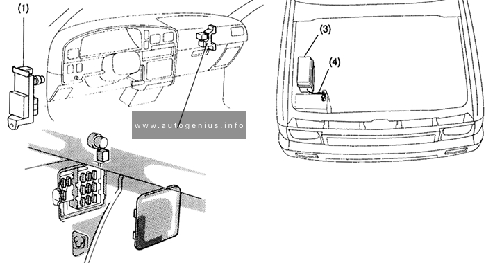
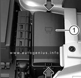
Relay Panels
The placement of auxiliary relay carriers and fuse carriers is not standardized; it varies depending on the specific equipment installed in the vehicle.
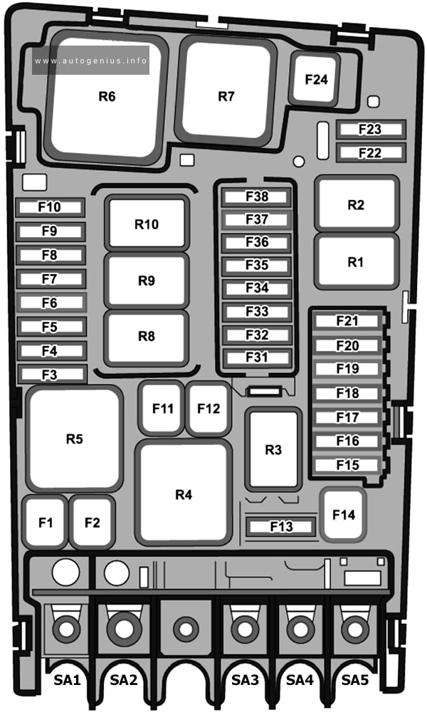
Relay carrier under driver seat
Assignment of the relays in the relay carrier
| № | Amps | Description |
|---|---|---|
| S171 | 15A | Battery isolation relay fuse |
| S41 | 30A | Heated rear window single fuse |
| S160 | 15A | Heated passenger’s seat fuse |
| S159 | 15A | Heated driver’s seat fuse |
| S161 | 10A | Trailer operation turn signal relay fuse |
| S188 | 10A | Roof mounted turn signals fuse |
| S187 | 15A | Differential lock fuse |
| S147 | 15A | Relief relay fuse |
| S37 | 25A | Power window fuse (driver’s side) |
| S170 | 25A | Fuse for electric windows (front passenger side) |
| S97 | 30A | Fresh air blower fuse |
| S23 | 25A | Heater fuse (Additional air heater B1LC/D1LC / B3LC/D3LC) |
| S53 | 60A | ABS hydraulic pump fuse/valves |
| S186 | 15A | Tilt device fuse |
| S136 | 15A | Air conditioning system fuse |
| S81 | 20A | Fuel pump fuse (Engine codes: AGL) |
| S42 | 20A | Radiator fan fuse |
| S254 | 15A | Optional equipment fuse (Additional exterior and interior installations) |
| S219 | 15A | Power take-off fuse |
| S219 | 15A | Power take-off/speed regulation fuse (Engine codes: AHD) |
| S82 | 10A | Continued circulation of coolant pump fuse (Engine codes: AHD, AGX, AGK) |
| S53 | 50A | ABS return flow pump fuse (ABS control unit) |
| S106 | 25A | Rotating light fuse |
| S150 | 20A | Headlight washer system fuse |
| S190 | 15A | Terminal 30 voltage supply fuse (Heated rear window delay relay, magnetic coupling control unit, battery split charge relay) |
| S148 | 10A | Mirror adjustment /heater fuse |
| S64 | 20A | Socket fuse |
| S124 | 7.5A | ABS control unit fuse |
| S124 | 10A | ABS control unit fuse |
| S220 | 7.5A | Daylight driving lights fuse (from May 1997) |
| S172 | 15A | Daylight driving light fuse (left dipped beam) |
| S174 | 15A | Daylight driving light fuse (left side and tail lights) (up to April 1997) |
| S175 | 15A | Daylight driving light fuse (right side and tail lights) (up to April 1997) |
| S49 | 15A | Siren fuse |
| S54 | 25A | ABS valves fuse |
| S51 | 10A | Warm air blower 1st and 2nd speeds fuse |
| S118 | 25A | Warm air blower and coolant shut-off valve fuse |
| S52 | 25A | Central locking fuse |
| S290 | 30A | Fuel filter heating fuse |
| S175 | 15A | Daylight driving light fuse (side and tail lights) (from May 1997) |
| S173 | 15A | Daylight driving light fuse (right dipped beam) |
Auxiliary relay carrier on the flap under the driver’s seat
Assignment of the relays in the relay carrier
| № | Designation/function |
|---|---|
| Terminal 15 relief relay | |
| Terminal D+ relief relay | |
| Fuel pump relay (Engine codes: AGL) | |
| Fresh air blower relay | |
| Air conditioning system switch-off relay | |
| Magnetic coupling relay | |
| Headlight washer system relay | |
| Horn relay | |
| Terminal 30 voltage supply relay (Engine codes: AHD, AGX) | |
| Daylight driving light relay (dipped beam) | |
| Daylight driving light relay (left dipped beam) (from May 1997) | |
| Daylight driving light relay (right dipped beam) (from May 1997) | |
| Daylight driving relay (side and tail lights) | |
| Magnetic coupling control unit (Engine codes: AGL) |
Auxiliary relay carrier and control units under driver’s seat at rear
Assignment of the relays in the relay carrier
| № | Designation/function |
|---|---|
| Battery split charge relay | |
| Trailer operation turn signal relay | |
| Roof mounted turn signals relay | |
| Daylight driving lights switch-on relay | |
| Rotating light relay | |
| Airbag/seat belt tensioner control unit | |
| CCS control unit (Engine codes: AGL) | |
| Coolant shortage indicator control unit (Discontinued from August 1998) | |
| Rotating light and siren system control unit | |
| Central locking control unit | |
| Diesel direct injection system control unit | |
| Motronic control unit (Engine codes: AGL 105 KW) | |
| Fuel filter heater relay | |
| Tilt device relay | |
| Magnetic coupling cut-out relay, air conditioning system | |
| Radiator fan relay | |
| Delay relay |
Relay carrier on right in engine compartment
Assignment of the relays in the relay carrier
| № | Description |
|---|---|
| – | Radiator fan 4th speed relay |
| – | Automatic intermittent wash/wipe and Hazard warning light relay control unit |
Relay carrier on left in engine compartment
Assignment of the relays in the relay carrier
| № | Amps | Designation/function |
|---|---|---|
| S39 | 80A | Strip fuse for glow plugs (Engine codes: AHD, AGX, AGK) |
| Glow plug relay (Engine codes: AHD, AGX) | ||
| Glow plug relay (Engine codes: AGK) | ||
| ABS with EDL control unit | ||
| Immobilizer control unit |