No.
|
A
|
Circuit Protected |
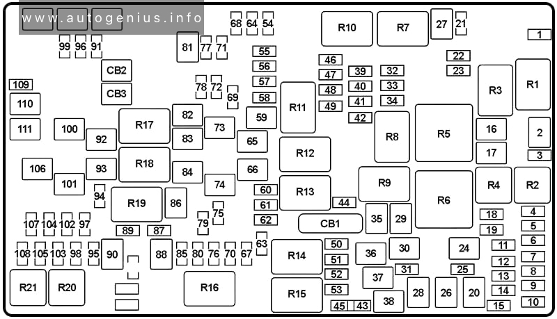
| 1 |
5 |
PHEV: HV Electric Coolant Heater Enable |
| 2 |
40 |
except PHEV: Starter |
| 3 |
5 |
Intelligent Battery Sensor (IBS) |
| 4 |
20 |
Fuel Pump Motor, Fuel Pump Control Module (FPCM) |
| 25 |
6.4L Hemi V8 (’18-’23): Fuel Pump |
| 5 |
5 |
Security Gateway |
| 6 |
15 |
PHEV: Battery Pack Control Module (BPCM) |
| 7 |
15 |
Wrangler: Low Temp Radiator Cooling Pump (LTR) |
| 15 |
PHEV: PECP-2
|
| 8 |
15 |
ZF 8HP75: Transmission Control Module (TCM) |
| 9 |
5 |
PHEV: Integrated Dual Charging Module (IDCM) |
| 10 |
15 |
Key Ignition Node (KIN), Radio Frequency Hub (RF HUB), Electric Steering Column Lock (ESCL) |
| 11 |
10 |
UCI Port (USB & AUX) |
| 12 |
25 |
HiFi Amplifier |
| 13 |
10 |
PHEV: Power Inverter Module (PIM) – Redundant Main Power Supply |
| 14 |
10 |
PHEV: Power Inverter Module (PIM) – Main Power Supply |
| 15 |
15 |
Instrument Panel Cluster (IPC), Switch Bank-Heavy Duty Electrical Pkg |
| 16 |
– |
– |
| 17 |
40 |
PHEV: Transmission Oil Pump |
| 18 |
10 |
Air Conditioning Clutch |
| 19 |
5 |
PHEV: Charge Port Indicator |
| 20 |
30 |
Interior Lights – Central Body Controller (CBC) |
| 21 |
20 |
Wrangler: Rear Wiper |
| 22 |
10 |
Engine Control Module (ECM)/Powertrain Control Module (PCM), Motor Generator Unit (MGU – Wrangler), Power Pack Unit (PPU – Wrangler), Power Inverter Module (PIM – PHEV) |
| 23 |
10 |
except PHEV: Engine Control Module (ECM)/Powertrain Control Module (PCM) |
| 24 |
30 |
’23-: Passenger’s Power Seat |
| 25 |
10 |
Module Shift By Wire |
| 26 |
40 |
Exterior Lights No.1 – Central Body Controller (CBC) |
| 27 |
30 |
Front Wipers |
| 28 |
40 |
Power Locks – Central Body Controller (CBC) |
| 29 |
40 |
Exterior Lights No.2 – Central Body Controller (CBC) |
| 30 |
30 |
’23-: Power Step/Slider |
| 31 |
10 |
Data Link Connector (DLC) |
| 32 |
10 |
Occupant Classification Module (OCM), Driver Presence Detection Module (DPDM), Heating Ventilation Air Conditioning (HVAC) Module, Steering Column Lock (SCL) |
| 33 |
10 |
ParkTronics System (PTS), Airbag Disable Lamps, Infrared Camera Module (IRCM) |
| 34 |
10 |
Electronic Stability Control (ESC), Electric Hydraulic Power Steering (EHPS), Smart Bar Control Module (SBCM) |
| 35 |
30 |
except PHEV: Brake Vacuum Pump |
| 36 |
30 |
Electric Brake Module (Trailer Tow) |
| 37 |
30 |
Trailer Tow Connector (7W) |
| 38 |
20 |
Engine Control Module (ECM) |
| 39 |
15 |
3.6L (Wrangler MHEV): Mild Hybrid Motor Generator Unit (MGU) Coolant Pump |
| 40 |
15 |
DriveTrain Control Module (DTCM), Axle Lock (FT/RR) |
| 41 |
15 |
Instrument Cluster (IC), Security GateWay (SGW) |
| 42 |
10 |
with Stop/Start: Power Control Relay Control Feed (except PHEV) |
| 43 |
20 |
Wrangler: Power Outlet – Batt (Cargo) (You can select to switch the Cargo Power Outlet from F43 battery fed power to this position F45 which is fed when the ignition in ON) |
| 44 |
10 |
InfraRed Camera (IRCAM) – Heaters |
| 45 |
20 |
Wrangler: Power Outlet – Ignition (Cargo) |
| 46 |
10 |
Headlamp Switch, Auto Headlamp Leveling Module, Headlamp Leveling Motors |
| 47 |
10 |
PHEV: Quiet Vehicle Pedestrian Module (QVPM) |
| 48 |
– |
– |
| 49 |
10 |
Occupant Restraint Controller (ORC) |
| 50 |
10 |
Heavy Duty (HD) Aссessory |
| 51 |
10 |
Wrangler: Digital TV (DSRC), USB, InSide RearView Mirror (ISRVM), Compass Module (CSGM), Inverter 400W (PHEV), Engine Control Module (ECM – PHEV), Power Inverter Module (PIM – PHEV) |
| 10 |
Gladiator: Humidity Light Rain Sensor (HLRS), Inverter 400W, USB, InSide RearView Mirror (ISRVM), Compass Module (CSGM), Digital TV (DTV) |
| 52 |
20 |
Cigarette Lighter |
| 53 |
10 |
Gladiator, PHEV: Wireless Speaker |
| 54 |
– |
– |
| 55 |
10 |
Wrangler (’22-): Central Vision Processing Module (CVPM) |
| 10 |
Gladiator: Central Vision Processing Module (CVPM) or Parktronics Module |
| 56 |
10 |
In Car Temperature Sensor, PTC Heater Coil (’20- (except PHEV)) |
| 57 |
20 |
Front Driver Heated Seat |
| 58 |
20 |
Front Passenger Heated Seat |
| 59 |
30 |
’23-: Driver Power Seat |
| 60 |
15 |
Heated Steering – Comfort Steering Wheel Module (CSWM) |
| 61 |
10 |
Left Blind Spot Sensor (LBSS), Right Blind Spot Sensor (RBSS), Central ADAS Decision Module (CADM Lo (’23-)) |
| 62 |
10 |
’22-: Exhaust Solenoid (except PHEV) |
| 63 |
10 |
Occupant Restraint Controller (ORC) |
| 64 |
– |
– |
| 65 |
50 |
Gladiator, PHEV: Power Inverter 400W |
| 66 |
40 |
Front Blower Motor (HVAC) |
| 67 |
15 |
PHEV: BCP – Lo Temp Active Pump |
| 68 |
– |
– |
| 69 |
5 |
Wrangler (’18-’23): Motor Generator Unit (MGU), Belt Starter Generator (BSG) |
| 10 |
’23-: KIN / RF Hub |
| 70 |
25 |
Gasoline: Injectors, Ignition Coils |
| 25 |
Diesel: Glow Plug Module |
| 71 |
10 |
PHEV: Battery Coolant Heater |
| 72 |
10 |
HD ELEC ACC PKG |
| 73 |
20 |
Wrangler: Power Top (LT) |
| 74 |
20 |
Wrangler: Power Top (RT) |
| 75 |
10 |
Wrangler (’18-’23): Belt Starter Generator (BSG), Power Pack Unit – Battery Pack Control Module & Auxiliary Power Module (PPUBPCM & APM) |
| 5 |
PHEV: Battery Charge Indicator, Switch Bank PHEV Mode |
| 76 |
20 |
Gasoline: Engine Control Module (ECM) |
| 20 |
Diesel: Powertrain Control Module (PCM) |
| 77 |
10 |
Heated Mirrors |
| 78 |
10 |
Wrangler: Computer, Intrusion Module, Siren, Intrusion Sensor |
| 79 |
20 |
Smart Bar Control Module |
| 80 |
15 |
Powertrain Control Module (PCM), Block Shift Solenoid No.1 & No.2 (Wrangler – ’22-), ELCM Module (PHEV), Fuel Tank Isolation Solenoid (PHEV) |
| 10 |
Wrangler (’22-’23): Vapor Blocking Valve (BSG) |
| 81 |
30 |
Rear Window Defogger (EBL) |
| 82 |
30 |
Diesel: Fuel Heater |
| 83 |
60 |
Diesel: Glow Plug |
| 50 |
PHEV: ESC-ECU & Valves
|
| 84 |
30 |
Diesel: Urea Heater Control Unit |
| 20 |
PHEV: Power Inverter Module (PIM) – High Side Drive Power |
| 85 |
10 |
’18-’23: PM Sensor |
| 15 |
PHEV: PECP – Lo Temp Passive Pump |
| 86 |
30 |
Wrangler (’18-’23): Brake Vacuum Pump No.2 |
| 87 |
10 |
’18-’23: Purging Pump Supply |
| 15 |
PHEV: AHP – High Temp Auxiliary Pump |
| 88 |
20 |
’18-’23: NOx Sensor No.1 & No.2 |
| 89 |
10 |
Steering Column Control Module (SCCM), Cruise Control, Digital TV (DTV), Electronic Vehicle Information Center (EVIC (’22-)), Airbag Disable Lamp (’20-) |
| 90 |
20 |
Parking Lamp (Trailer Tow) |
| 91 |
20 |
Horn |
| 92 |
40 |
Heavy Duty (HD) Accessory No.2 |
| 93 |
40 |
Heavy Duty (HD) Accessory No.1 |
| 94 |
10 |
’18-’21: Tire Pressure Monitor (TPM), RF Hub System (CORAX) |
| 10 |
’23-: Red Dual USB Port |
| 95 |
– |
– |
| 96 |
10 |
Power Mirror Switch |
| 97 |
20 |
Radio, Telematic Box Module (TBM) |
| 98 |
10 |
Off Road, Switch Bank (Heavy Duty Electrical) |
| 99 |
– |
– |
| 100 |
30 |
except PHEV: Electronic Stability Control (ESC) Control Unit & Valves |
| 101 |
30 |
DriveTrain Control Module (DTCM) |
| 102 |
15 |
’18-’23: Dual USB Port |
| 15 |
’23-: TBM2 / DCSD Mod |
| 103 |
15 |
Heavy Duty (HD) Accessory No.3 |
| 104 |
15 |
’18-’23: PPU Cool Pump |
| 15 |
’23-: Power Seat Lumbar Switch (Driver & Passenger) |
| 105 |
10 |
Integrated Center Stack (ICS), Heat Ventilation Air Conditioning (HVAC), ETC (’23-) |
| 106 |
40 |
’18-’22: Electronic Stability Control (ESC) Pump Motor |
| 50 |
’22-: Electronic Stability Control (ESC) Pump Motor |
| 107 |
20 |
Left Stop & Turn Lamps (Trailer Tow) |
| 108 |
15 |
Heavy Duty (HD) Accessory No.4 |
| 109 |
20 |
Right Stop & Turn Lamps (Trailer Tow) |
| 110 |
30 |
Power Inverter 150W |
| 111 |
20 |
Backup Lamps (Trailer Tow) |
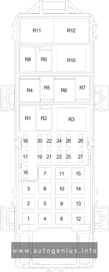
| Relay |
| R1 |
|
| R2 |
|
| R3 |
|
| R4 |
|
| R5 |
|
| R6 |
|
| R7 |
|
| R8 |
|
| R9 |
|
| R10 |
|
| R11 |
|
| R12 |
|
| R13 |
|
| R14 |
|
| R15 |
|
| R16 |
|
| R17 |
|
| R18 |
|
| R19 |
|
| R20 |
|
| R21 |
|