Volkswagen Multivan (T6.1; 2019 – 2021) – fuse and relay box diagram
Year of production: 2019, 2020, 2021
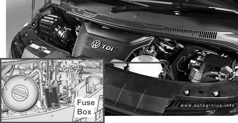
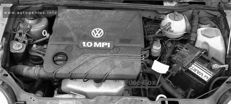
The Volkswagen Caravelle and Multivan are nearly identical both technically and externally, with the primary difference being in the interior trim and panels. Both models are built on the same platform as the VW Transporter and serve as its passenger variants. This article focuses on the seventh-generation Volkswagen Multivan (T7), produced from 2022 to 2024, and the facelifted sixth-generation Volkswagen Transporter/Multivan (T6.1), produced from 2019 to 2021. Here, you’ll find information about the location of the fuse panels and learn about the function and layout of each fuse and relay.
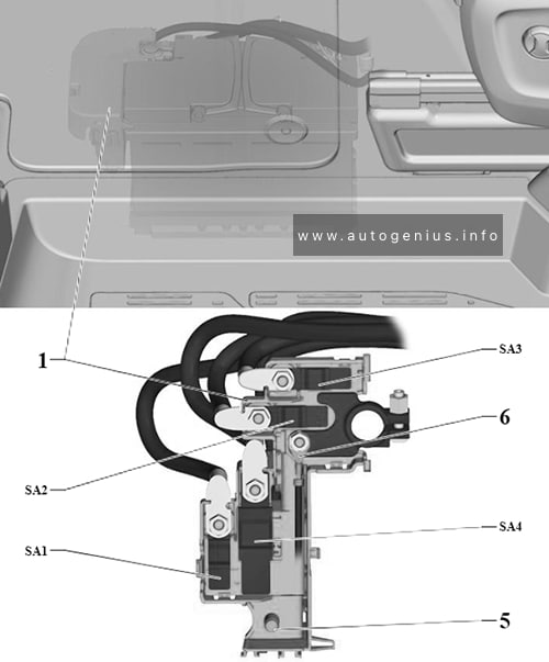
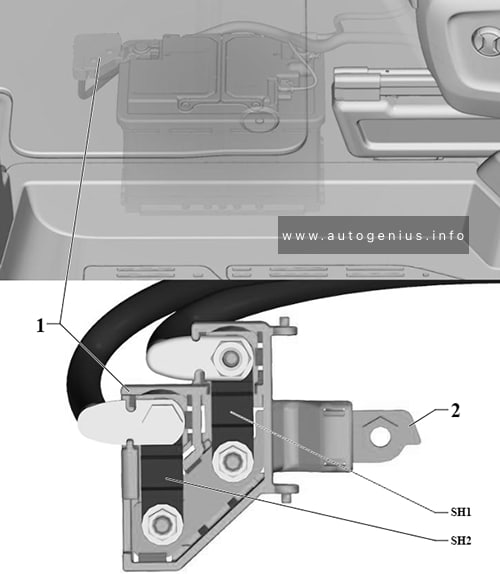
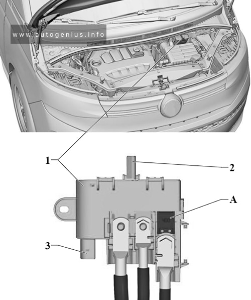
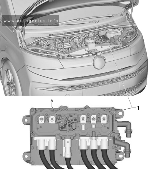
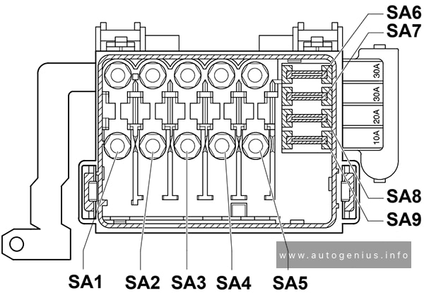
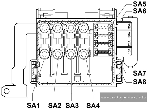
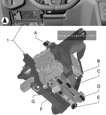
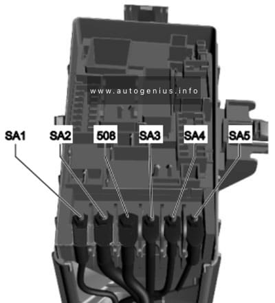
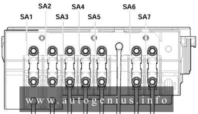
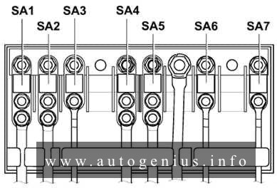
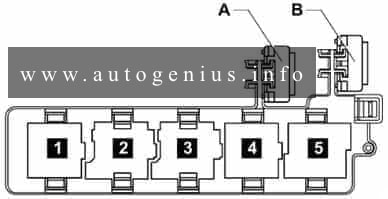
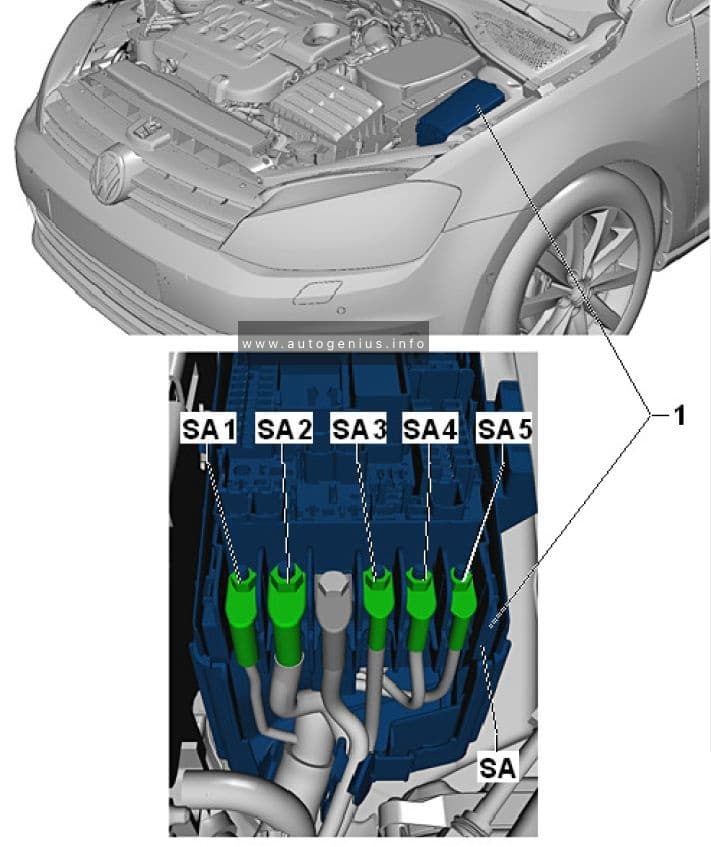
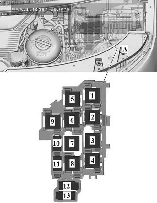
Fuse Holder A
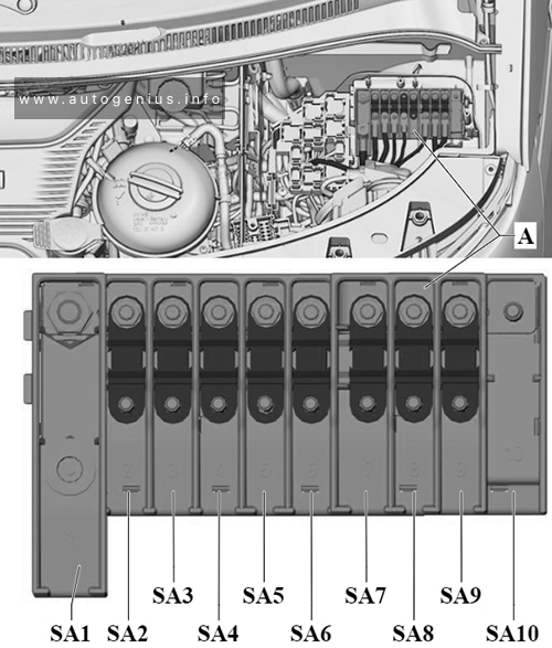
Assignment of the fuses in the Fuse Holder A
| № | Amps | Function/component |
|---|---|---|
| SA1 | 225A | Alternator with voltage regulator -CX1- (For models with an alternator with voltage regulator -CX1- (140A/180A) and without a second battery) |
| SA2 | 125A | X-contact relay -J18- – Fuses on fuse holder C: 55, 56, 57, 61 Terminal 15 voltage supply relay -J329- – Fuses on fuse holder C: 9, 10, 39, 40, 42, 43, 44, 46 Fuses on fuse holder C: 1, 28, 29, 30, 31, 32, 33, 34, 35, 36, 37, 53, 60, 61 |
| SA3 | 100A | Fuses in fuse holder H: 1, 2, 3, 5, 6, 7, 8, 9, 10, 11, 12, 17, 18, 19, 20, 25, 26, 27, 28 |
| SA4 | 80A | Main relay-J271- : – Fuses on fuse holder B: 1, 7, 10, 12, 14, 16, 19, 21, 23, 25, 27, 28, 29, 31, 32, 33 Fuses on fuse holder B: 2, 4, 5, 6, 9, 11, 13, 18, 30, 34 |
| SA5 | 60A | ABS control unit -J104- : |
| SA6 | 125A | Power steering control unit -J500- : |
| SA7 | 100A | Radiator fan -VX57- (For models with an alternator with voltage regulator -CX1- (140A/180A) and without a second battery) Fuse 1 on fuse holder M -SM1- (For models with an alternator with voltage regulator -CX1- (140A/180A) and without a second battery) |
| SA8 | 100A | Automatic glow period control unit -J179- (For models with an alternator with voltage regulator -CX1- (140A/180A) and without a second battery) Heated windscreen relay -J47- (For models with an alternator with voltage regulator -CX1- (140A/180A) and without a second battery) – Fuses on fuse holder B: 8, 26 |
| SA9 | 125A | Rear left turn signal additional relay -J420- – Left roof mounted turn signal bulb -M23- Rear right turn signal additional relay -J421- – Right roof mounted turn signal bulb -M24- Fuses on fuse holder C: 2, 3, 4, 5, 6, 7, 8, 11, 12, 13, 14, 15, 16, 17, 18, 19, 20, 21, 22, 23, 24, 25, 26, 27, 38, 47, 48, 50, 51, 52, 54, 58 |
| SA10 | – | Connection for battery -A- |
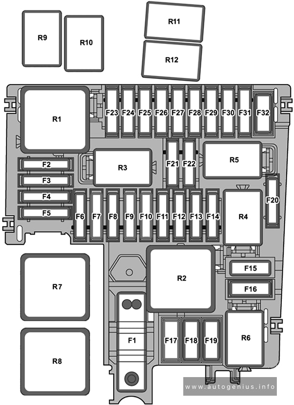
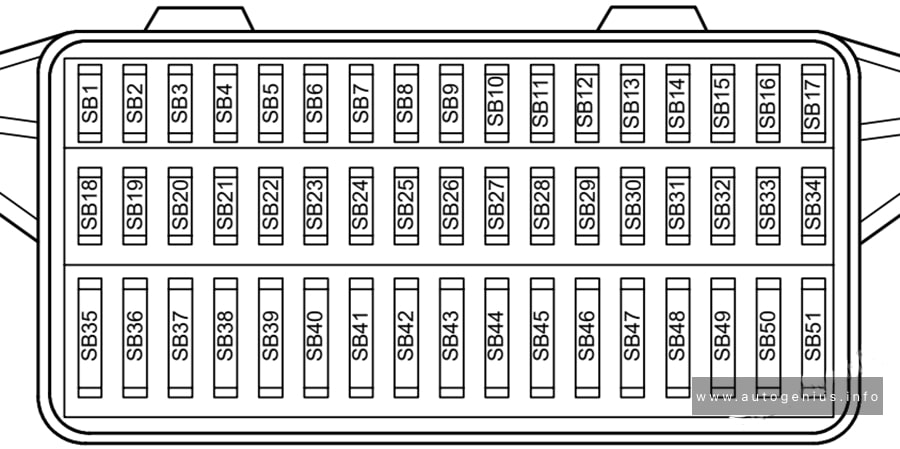
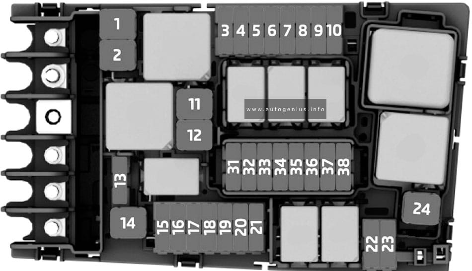
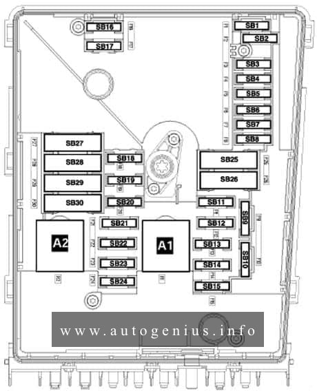
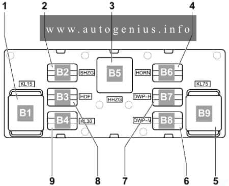
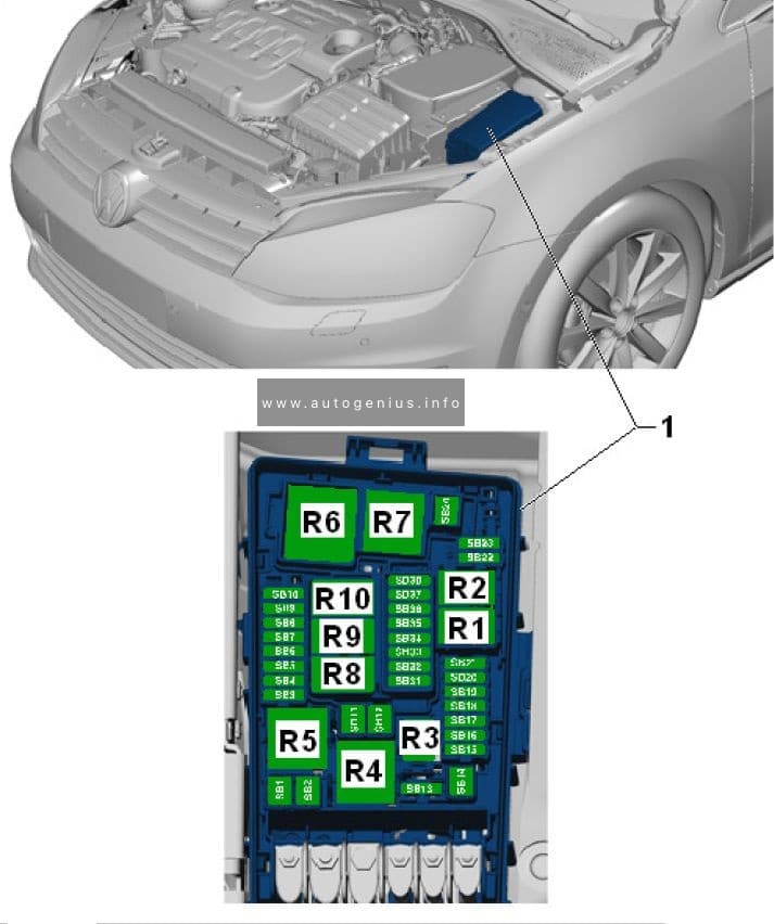
Fuse Holder B
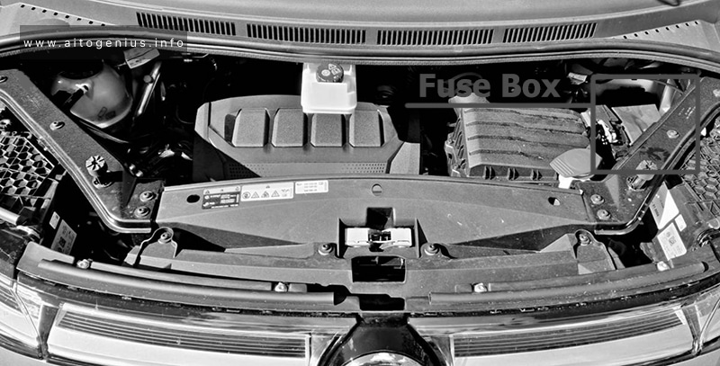
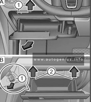
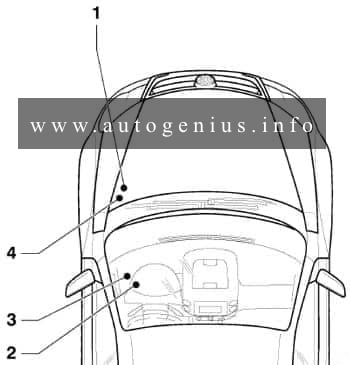
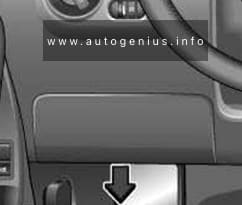
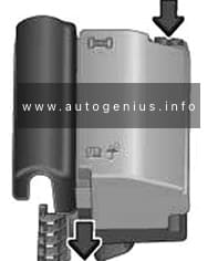
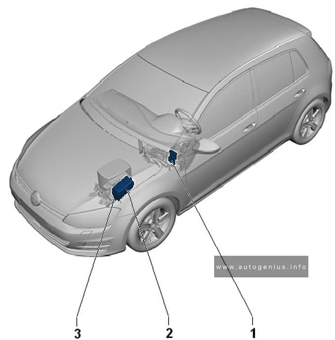
Fuse Box Location

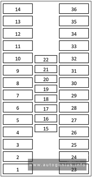
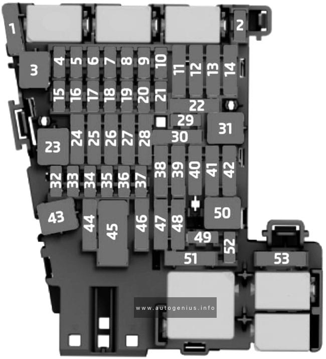
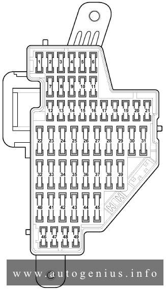
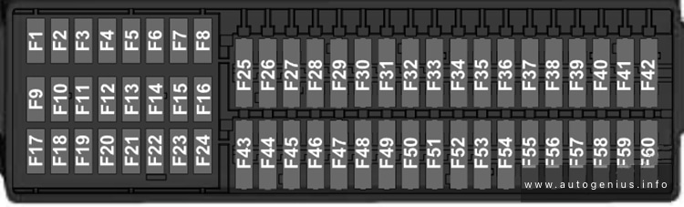
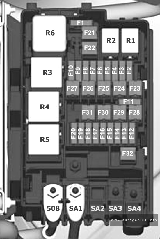
Fuse box diagram

Assignment of the fuses in the Fuse Holder B
| № | Amps | Function/component |
|---|---|---|
| SB1 | 5A | Radiator fan -VX57- |
| SB2 | 30A | ABS control unit -J104- |
| SB3 | – | – |
| SB4 | 10A | Brake light additional relay -J419- – High-level brake light bulb -M25- |
| SB5 | 10A | Selector lever sensors control unit -J587- Mechatronic unit for dual clutch gearbox -J743- Ignition key withdrawal lock solenoid -N376- |
| SB6 | 10A | ABS control unit -J104- |
| SB7 | 5A | Heater element for crankcase breather -N79- |
| SB8 | 30A | Heated windscreen -Z2- |
| SB9 | 5A | Engine control unit -J623- |
| 15A | Engine control unit -J623- | |
| SB10 | 10A | Charge pressure control solenoid valve -N75- Charge pressure control solenoid valve 2 -N274- Intake manifold flap valve -N316- Turbine changeover valve -N529- |
| 10A | Charge pressure control solenoid valve 2 -N274- Solenoid for coolant circuit -N492- Turbine changeover valve -N529- |
|
| SB11 | 10A | Magnetic clutch relay -J44- – Air conditioner compressor -VX81 – |
| SB12 | 10A | Fuel pressure regulating valve -N276- |
| 10A | Fuel metering valve -N290- | |
| SB13 | 10A | Relay for reducing agent metering system -J963- – Delivery unit for reducing agent metering system -GX19- – Reducing agent tank -VX85- |
| SB14 | 5A | Fuel pump relay -J17- – Fuel delivery unit -GX1- |
| 30A | Fuel pump control unit -J538- – Fuel delivery unit -GX1- |
|
| SB15 | 5A | Reversing light switch -F4- |
| SB16 | 5A | Brake light switch -F- |
| SB17 | 5A | Centre switch module 3 in dash panel -EX48- |
| SB18 | 5A | Heated windscreen relay -J47- |
| SB19 | 5A | Air mass measurement module -GX35- Clutch position sender-G476- |
| 5A | Clutch position sender -G476- | |
| SB20 | 5A | Engine/motor control unit -J623- |
| SB21 | 5A | Reducing agent tank -VX85- Control unit for reducing agent heater -J891 – |
| SB22 | 10A | Auxiliary coolant heater relay -J493- (up to June 2021) – Heater coolant shut-off valve -N279- (up to June 2021) Auxiliary coolant heater coolant circuit valve relay -J575- (up to June 2021) – Heater coolant shut-off valve -N279- (up to June 2021) |
| SB23 | 10A | Relay for reducing agent metering system -J963- |
| SB24 | 5A | Selector lever sensors control unit -J587- Mechatronic unit for dual clutch gearbox -J743- |
| SB25 | 5A | Oil level and oil temperature sender -G266- |
| SB26 | 30A | Heated windscreen -Z2- |
| SB27 | 10A | Charge air cooling pump -V188- Pump for exhaust gas recirculation cooler -V400- |
| SB28 | 15A | Control unit for NOx sender -GX30- Control unit 2 for NOx sender -GX46- Control unit 3 for NOx sender -GX50- Control unit 1 for particulate sensor-GX52- |
| SB29 | 5A | Valve for oil pressure control -N428- Auxiliary pump for heating -V488- |
| 15A | Valve for oil pressure control -N428- Charge air cooling pump -V188- Pump for exhaust gas recirculation cooler -V400- Auxiliary pump for heating -V488- |
|
| SB30 | 20A | Fuel pump relay -J17- – Fuel delivery unit -GX1- |
| SB31 | 15A | Lambda probe 1 before catalytic converter -GX10- |
| SB32 | 30A | Engine/motor control unit -J623- |
| SB33 | 5A | Automatic glow period control unit -J179- |
| SB34 | 5A | Data bus diagnostic interface -J533- |
| SB35 | – | – |
| SB36 | – | – |
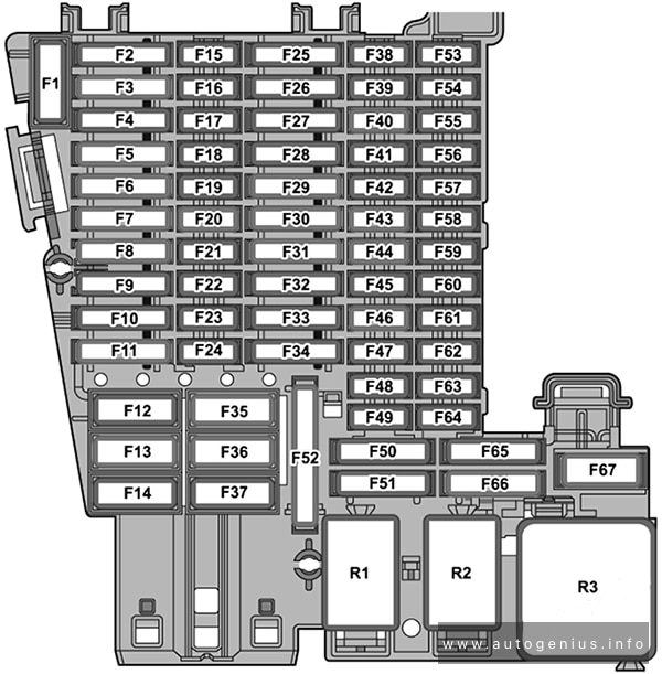
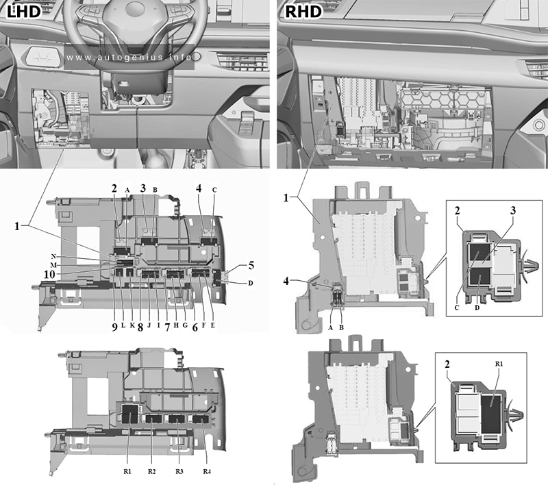
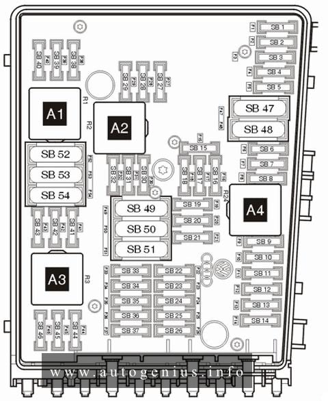
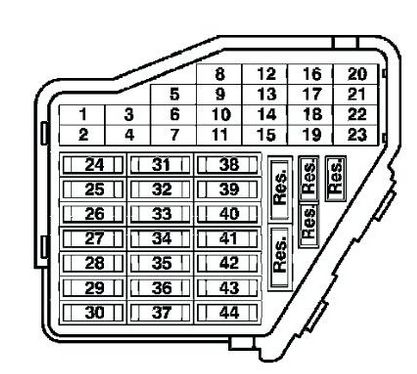
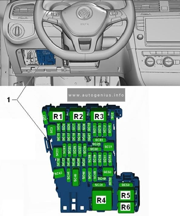
Fuse Holder C
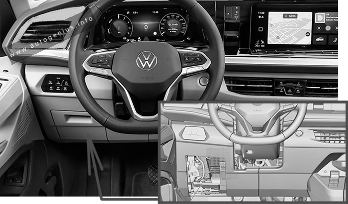
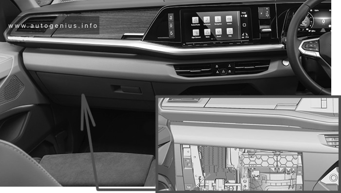
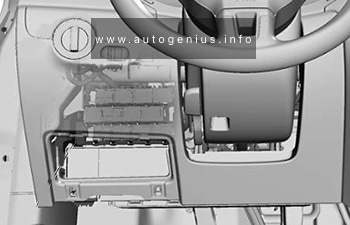
Fuse Box Location
Left-hand drive vehicle.

Right-hand drive vehicle

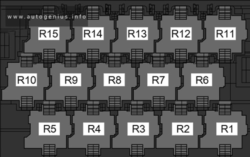
Fuse Box Diagram
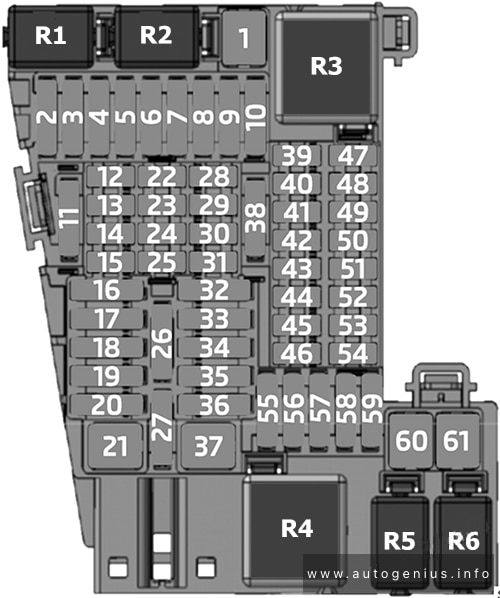
Assignment of the fuses in the Fuse Holder C
| № | Amps | Function/component |
|---|---|---|
| 1 | 40A | Fresh air blower control unit -J126- – Fresh air blower -V2- |
| 2 | 30A | Switch module for front passenger seat -E664- (right-hand drive models) Driver seat adjustment control unit -J810- (left-hand drive models) |
| 3 | 30A | Switch module for front passenger seat -E664- (left-hand drive models) Driver seat adjustment control unit -J810- (right-hand drive models) |
| 4 | 20A | Front passenger seat lumbar support adjustment switch -E177- Front left lumbar support adjustment switch -E752- Front right lumbar support adjustment switch -E753- |
| 5 | 25A | Special vehicle control unit -J608- |
| 6 | 25A | Special vehicle control unit -J608- |
| 7 | 25A | Special vehicle control unit -J608- |
| 8 | 25A | Special vehicle control unit -J608- |
| 9 | 30A | Starter relay 1 -J906- Starter relay 2 -J907- – Starter -B- |
| 10 | 30A | Fuse 15 on fuse holder B -SB15- Fuse 17 on fuse holder B -SB17- Fuse 20 on fuse holder B -SB20- Fuse 24 on fuse holder B -SB24- |
| 11 | 20A | Auxiliary heater control unit -J364- |
| 12 | 7.5A | Operating and display unit for rear air conditioning system -E265- Additional display and operating unit 1 -E857- Heater and air conditioning controls -EX21- Remote control receiver for auxiliary heater -R64- |
| 13 | 5A | Steering column combination switch -E595- |
| 14 | 7.5A | Circulation pump relay -J160- – Circulation pump -V55- |
| 15 | 10A | USB connection 1 -U41- USB charging socket for seat row 3, left -U100- |
| 16 | 30A | Onboard supply control unit -J519- – Windscreen wiper motor -V- |
| 17 | 25A | Front left headlight -MX1- |
| 18 | 5A | Rear left power latching motor -V307- Rear right power latching motor -V308- |
| 30A | Fuse 1 on fuse holder K -SK1- Fuse 2 on fuse holder K -SK2- Fuse 3 on fuse holder K -SK3- Fuse 4 on fuse holder K -SK4- |
|
| 19 | 15A | Terminal 15 voltage supply relay 2 -J681- – Electrical terminal strip for external use -TV65- |
| 20 | 30A | Onboard supply control unit -J519- Heated rear window relay -J9- – Heated rear window -Z1 – – Heated rear window in left wing door -Z26- – Heated rear window in right wing door -Z27- |
| 21 | 40A | Onboard supply control unit -J519- – Exterior lighting |
| 22 | 10A | Tachograph -G24- |
| 23 | 10A | Steering column combination switch -E595- |
| 24 | 5A | Anti-theft alarm sensor -G578- Interior monitoring sensor 2 -G592- Alarm horn -H12- |
| 25 | 5A | Rain sensor -G213- |
| 26 | 30A | Driver door control unit -J386- (left-hand drive models) Front passenger door control unit -J387- (right-hand drive models) |
| 27 | 30A | Driver door control unit -J386- (right-hand drive models) Front passenger door control unit -J387- (left-hand drive models) |
| 28 | 5A | Data bus diagnostic interface -J533- |
| 29 | 10A | Diagnostic connection -U31- |
| 30 | 5A | Rotary light switch -EX1- |
| 31 | 5A | Steering column combination switch -E595- |
| 32 | 20A | Control unit 1 for information electronics -J794- |
| 33 | 25A | Front right headlight -MX2- |
| 34 | 30A | Control unit for reducing agent heater -J891- |
| 35 | 25A | Electrical terminal strip for external use -TV65- |
| 36 | 30A | Onboard supply control unit -J519- – Horn or dual tone horn -H1- – Bass horn -H7- |
| 37 | 40A | Onboard supply control unit -J519- – Exterior lighting |
| 38 | 25A | Onboard supply control unit -J519- – Exterior lighting – Interior lighting – Internal supply |
| 39 | 10A | Airbag control unit -J234- Warning lamp for airbag deactivated on front passenger side -K145- |
| 40 | 10A | Mirror adjustment switch -E43- Headlight range control regulator -E102- Rear fresh air blower switch -E179- Centre switch module in dash panel -EX22- Oil level and oil temperature sender -G266- Pressure sender for refrigerant circuit -G805- Parking aid control unit -J446- Coolant shut-off valve relay -J541- – Climatronic coolant shut-off valve -N422- Voltage supply relay 2 -J710- Front left headlight -MX1- Front right headlight -MX2- Diagnostic connection -U31- Left washer jet heater element -Z20- Right washer jet heater element -Z21- |
| 41 | 10A | not assigned |
| 42 | 7.5A | Rotary light switch -EX1- Accident data recorder button -E497- Steering column combination switch -E595- Interior mirror -EX5- Tachograph -G24- Adaptive cruise control unit -J428- Terminal 15 voltage supply relay 2 -J681- Accident data memory -J754- Control unit for external vehicle communication -J1262- Front camera for driver assist systems -R242- Automatic anti-dazzle interior mirror -Y7- |
| 43 | 10A | Differential lock control unit -J187- Vacuum switch for rear differential lock -F363- |
| 44 | 10A | Accident data recorder button -E497- Accident data memory -J754- Control unit for ignition bypass -J905- 10-pin connector -T10ce- 12-pin connector -T12f- |
| 10A | Taximeter -G41- Mirror taximeter -G511- Two-way radio -R8- |
|
| 45 | 10A | Interface control unit for telematics -J1221- |
| 46 | 5A | Lane change assist control unit -J769- Lane change assist control unit 2 -J770- |
| 47 | 10A | Ignition/starter switch -D- – Onboard supply control unit -J519- – Special vehicle control unit -J608- – Engine/motor control unit -J623- |
| 48 | 10A | Accident data memory -J754- |
| 49 | 10A | Interface control unit for telematics -J1221- |
| 50 | 5A | Emergency call module control unit and communication unit -J949- |
| 51 | 5A | Dash panel insert -KX2- – Control unit in dash panel insert -J285- |
| 52 | 10A | Tyre Pressure Monitoring System control unit -J502- |
| 53 | 10A | Display unit for front information display and operating unit control unit -J685- Reversing camera system control unit -J772- Two-way signal amplifier for mobile telephone/data services -J984- Reversing camera -R189- Storage compartment with interface for mobile telephone -R265- |
| 54 | 10A | Onboard supply control unit -J519- – heated exterior mirror |
| 55 | 25A | Heated front seats control unit -J774- |
| 56 | 5A | Terminal 75 voltage supply relay 1 -J680- |
| 57 | 15A | Rear window wiper motor -V12- |
| 25A | Rear left wing door window wiper motor -V92- Rear right wing door window wiper motor -V93- |
|
| 58 | 15A | Electronically controlled damping control unit -J250- |
| 59 | – | – |
| 60 | 40A | Onboard supply control unit -J519- – Central locking |
| 61 | 40A | Rear fresh air blower switch -E179- – Rear fresh air blower -V80- |
| 40A | Rear fresh air blower control unit -J391- – Rear fresh air blower -V80- |
|
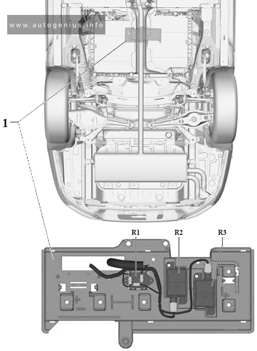
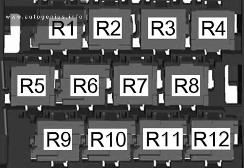
| R1 | Terminal 15 voltage supply relay 2 -J681- | |
| R2 | Circulation pump relay -J160- | |
| R3 | Terminal 15 voltage supply relay -J329- | |
| R4 | X-contact relay -J18- | |
| R5 | Rear left turn signal additional relay -J420- | |
| R6 | Rear right turn signal additional relay -J421- | |
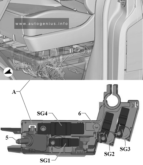
Fuse Holder G

Assignment of the fuses in the Fuse Holder G
| № | Amps | Function/component |
|---|---|---|
| 1 | 200A | Fuses on fuse holder G: 2, 3, 4 Battery monitor control unit 2 -J934- Second battery -A1- |
| 2 | 60A | Fuses in fuse holder H: 4, 5, 6, 7, 8, 9, 10, 11, 12 |
| 3 | 60A | for models with equipment for California: Fuses in fuse holder H: 13, 14, 15, 16, 25, 26 |
| 100A | for models with police equipment: Fuses in fuse holder H: 21, 22, 23, 24, 25, 26 Fuses on fuse holder F: 1, 2 -SF1- (from November 2020) |
|
| 4 | 100A | for models with equipment for California: Battery monitor control unit 3 -J1116- Battery fuse in special vehicle -S339- – Battery for special vehicle -A24- |
| 300A | Body manufacturer |
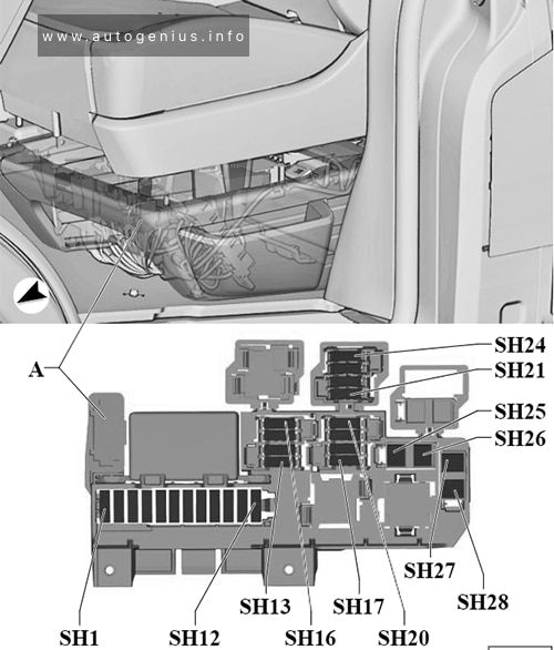
Fuse Holder H

Assignment of the fuses in the Fuse Holder H
| № | Amps | Function/component |
|---|---|---|
| 1 | 30A | Trailer detector control unit -J345- |
| 2 | 30A | Trailer detector control unit -J345- |
| 3 | 30A | Trailer detector control unit -J345- |
| 4 | 20A/25A | Auxiliary air heater control unit -J604- |
| 5 | 30A | Trailer detector control unit -J345- |
| 6 | 20A | Cigarette lighter -U1- 12 V socket -U5- |
| 7 | 20A | 12 V socket 3 -U19- 12 V socket 4 -U20- 12 V socket 5 -U26- 12 V socket 6 -U33- 12 V socket 7 -U117- 12 V socket 8 -U118- |
| 10A | Switch-over relay 1 for roof ventilator -J180- – Roof ventilator -V3- |
|
| 8 | 10A | Switch-over relay 1 for roof ventilator -J180- – Roof ventilator -V3- |
| 10A | Switch-over relay 1 for roof ventilator -J180- – Roof ventilator -V3- |
|
| 15A | USB charging socket 1 -U37- | |
| 15A | Rotating light relay -J326- Rotating light control unit -J1114- – Coupling point on left B-pillar, bottom -TBL- – Coupling point for roof, left -THL- |
|
| 20A | 12 V socket 2 -U18- | |
| 20A | Rear interior light 4 -WX6- 12 V socket 2 for special vehicles -U84- |
|
| 9 | 10A | Front stop command light -G954- Flashing lights relay -J630- 10-pin connector -T10ce- Coupling point for roof, right -THR- Coupling point for roof, left -THL- |
| 15A | 12 V socket 5 -U26- 12 V socket 6 -U33- USB charging socket 1 for special vehicles -U91- |
|
| 20A | USB charging socket 2 -U38- 12 V socket 7-U117- 12 V socket 8-U118- |
|
| 10 | 10A | End position button for cupboard light -E905- Electric torch -R280- Surround lighting 1 in rear lid -W61- Surround lighting 2 in rear lid -W62- |
| 20A | 12 V socket for special vehicles -U83- 12 V socket 3 for special vehicles -U85- |
|
| 11 | 15A | Coupling point for roof, left -THL- Reading light for pull-out table -W24- Rear lid light 2 -W101- Rear interior light 4 -WX6- |
| 30A | Onboard charging unit -A11 – | |
| 12 | 5A | Operating and display unit for camping equipment -E153- |
| 5A | Taximeter -G41- Mirror taximeter -G511- |
|
| 15A | Two-way radio voltage relay -J84- | |
| 25A | Two-way radio voltage relay -J84- | |
| 13 | 30A | Relay to close convertible roof -J238- Relay to open convertible roof -J239- – Hydraulic pump motor -V401- |
| 14 | 30A | Onboard charging unit -A11- |
| 15 | 5A | Left front reading light button -E633- Rear illumination bulb -L153- Left rear interior light -W47- Rear right interior light -W48- |
| 16 | 7.5A | Kitchen background lighting -W122- |
| 17 | 20A | All-wheel drive control unit -J492- |
| 18 | 5A | Differential lock control unit -J187- |
| 19 | 10A | Power latching control unit -J657- |
| 30A | Rear lid control unit -J605- | |
| 20 | 5A | Voltage supply relay 1 -J701- Voltage supply relay 2 -J710- – Parking aid control unit -J446- |
| 21 | 20A | Operating unit for special signals -E507- |
| 22 | 15A | Operating unit for special signals -E507- |
| 23 | 10A | Rotating light relay -J326- – 12-pin connector -T12f- |
| 24 | 15A | Control unit for ignition bypass -J905- Terminal 75 voltage supply relay 1 -J680- – 10-pin connector -T10cg- – Charging station for hand-held 2-way radio -U24- |
| 25 | 40A | DC/AC converter with socket, 12 V – 230 V -U13- |
| 26 | 40A | Fuse 5 on fuse holder C -SC5- Fuse 7 on fuse holder C -SC7- – Special vehicle control unit -J608- |
| 27 | 40A | Rear driver side door control unit -J926- (For left-hand drive models) Passenger side rear door control unit -J927- (For right-hand drive models) |
| 28 | 40A | Rear driver side door control unit -J926- (For right-hand drive models) Passenger side rear door control unit -J927- (For left-hand drive models) |
| 1 | Battery isolation relay -J7- | |
| 2 | Switch-over relay 1 for roof ventilator -J180- (For models with roof ventilator) | |
| Rotating light relay -J326- (For models with special police equipment) | ||
| Voltage supply relay 1 -J701- (For right-hand drive models) | ||
| Rotating light control unit -J1114- (For models with rotating lights (yellow)) | ||
| 3 | Switch-over relay 1 for roof ventilator-J180- (For models with roof ventilator) | |
| Flashing lights relay -J630- (For models with special police equipment) | ||
| Voltage supply relay 2 -J710- (For right-hand drive models) | ||
| Rotating light control unit -J1114- (For models with rotating lights (yellow)) | ||
| 4 | not assigned | |
| 5 | Heated rear window relay -J9- | |
| 6 | Differential lock control unit -J187- | |
| 7 | Voltage supply relay 1 -J701- (For left-hand drive models) | |
| Flashing lights relay 2 -J890- (For models with special police equipment) | ||
| 8 | Two-way radio voltage relay -J84- (For models with special police equipment) | |
| Voltage supply relay 2 -J710- (For left-hand drive models) | ||
| 9 | Relay to close convertible roof -J238- (For models with camping equipment) | |
| 10 | Relay to open convertible roof -J239- (For models with camping equipment) | |
| 11 | Terminal 75 voltage supply relay 1 -J680- (For models with special police equipment) | |
| 12 | Switch-over relay 2 for roof ventilator -J181- (For models with roof ventilator) | |
| Rotating light relay -J326- (For models with rotating lights (yellow)) | ||
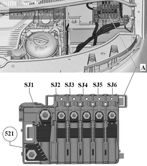
Fuse Holder J

Assignment of the fuses in the Fuse Holder J
| № | Amps | Function/component |
|---|---|---|
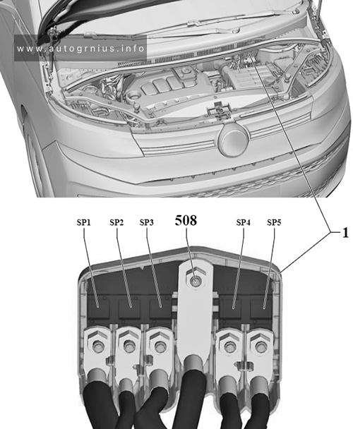
| SJ1 | 400A | Battery -A- |
| SJ2 | 200A | Battery isolation relay -J7- – Fuse 1 on fuse holder G -SG1- |
| SJ3 | 100A | Radiator fan -VX57- Fuse 1 on fuse holder M -SM1- |
| SJ4 | 100A | Automatic glow period control unit -J179- Heated windscreen relay -J47- – Fuse 8 on fuse holder B -SB8- – Fuse 26 on fuse holder B -SB26- |
| SJ5 | 200A | not assigned |
| SJ6 | 200A | not assigned |
| 521 | Connection for alternator with voltage regulator -CX1- |
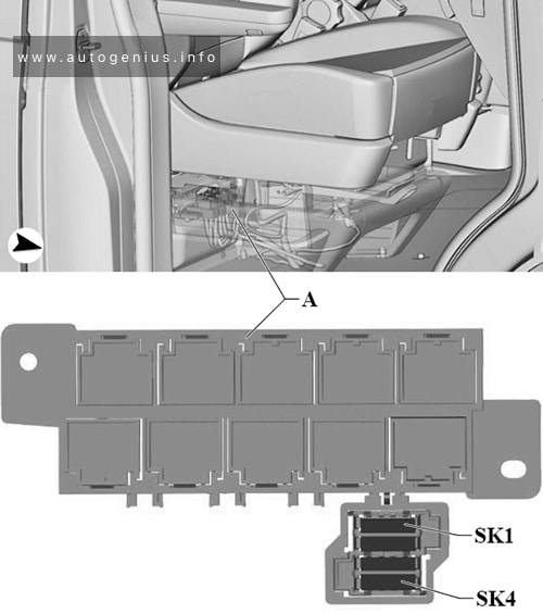
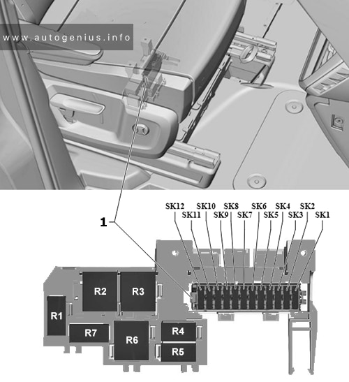
Fuse Holder K

Assignment of the fuses in the Fuse Holder K
| № | Amps | Function/component |
|---|---|---|
| SK1 | 15A | Rear right power latching motor -V308- |
| SK2 | 5A | Rear driver side active door protection control unit -J1093- (For right-hand drive models) Rear passenger side active door protection control unit -J1094- (For left-hand drive models) |
| SK3 | 15A | Rear left power latching motor -V307- |
| SK4 | 5A | Rear driver side active door protection control unit -J1093- (For left-hand drive models) Rear passenger side active door protection control unit -J1094- (For right-hand drive models) |
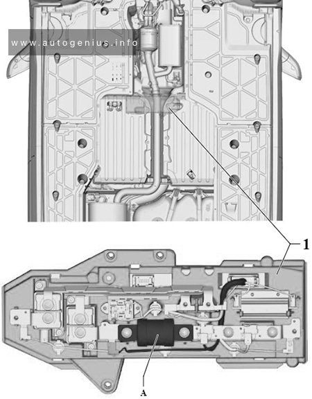
Fuse Holder M
(For models with hybrid drive).
Assignment of the fuses in the Fuse Holder M
| № | Amps | Function/component |
|---|---|---|
| 1 | Automatic glow period control unit -J179- | |
| 2 | Starter relay 2 -J907- | |
| 3 | not assigned | |
| 4 | Heated windscreen relay -J47- | |
| 5 | Main relay -J271- | |
| 6 | Coolant shut-off valve relay -J541- | |
| 7 | Brake light additional relay -J419- | |
| 8 | Fuel pump relay -J17- | |
| Auxiliary coolant heater relay -J493- | ||
| Auxiliary coolant heater coolant circuit valve relay -J575- | ||
| 9 | Starter relay 1 -J906- | |
| 10 | Magnetic clutch relay -J44- | |
| 11 | Relay for reducing agent metering system -J963- | |
| 12 | Fuel pump relay -J17- | |
| 13 / -SM1- | 40A | Control unit for reducing agent heater -J891- |
WARNING: Terminal and harness assignments for individual connectors will vary depending on vehicle equipment level, model, and market.